📱 Elevate Your Projects with Touchscreen Brilliance!
The HiLetgoILI9341 2.8" SPI TFT LCD Display Touch Panel features a high-resolution 240x320 display with a robust PCB design, making it an ideal choice for developers looking to enhance their projects with vibrant visuals and intuitive touch capabilities.
K**K
Works with Teensy 3.2 or Arduino - here's how:
I love these displays and use them on all my projects. I've bought about 8 so far and can get them to work with either Teensy 3.2 or an Arduino Nano.For operation with a Teensy 3.21. use the <ILI9341_t3.h> from the PJRC--and this lib is very fast connect directly2. for touch use "UTouch.h"3. for SD I use <SdFat.h>4. no level shifters needed5. you may need to solder J1 (I do on all my displays)4. if you want to use SD, remove the resistors R1, R2, R3 and solder 0 ohm resistorsFor operation with Auduino Nano1. use the <Adafruit_ILI9341.h>2. for touch use "UTouch.h"3. for SD I have yet to get an SD to work with graphics due to not enough memory4. no level shifters needed5. you WILL need to solder J1 (I do on all my displays)EDIT as of 12/29/2019 Usage with Arduino connect as usual but power your Arduino with 3.3 volts (just connect 3.3 to the 5V pin on the arduino). Alternatively you can put a 1K series resistor on all pins to drop the voltage going to the unit (and power with 3v3). THESE UNITS WILL NOT WORK IF POWERED WITH 5 AND IF THE SIGNAL LINES ARE 5 VOLTS.update 2/2/2022 tips on usage to get everything working on a teensy 4.0 (or 3.2)/*This simple program will test1) the display, 2) the SD card, 3) the touch screen, 4) ability to readPixelThe readPixel is only supported by some display driverslike the ILI9341_t3 driver, there is a PrintScreen.h utility that will let yousave your screen to a BMP file and draw the fileif readPixel fails try to adjust speeds above. It's possible the display MISO is not tri stateand will basically own MISO where other devices can't use it. If so, you will need some external buffermagicIf using display with Teensy (3v3) solder J1, replace R1, R2, R3 with 0 ohmpin connectionsDisplay MCUVCC 3v3GND GNDCS 10RESET 3v3 If white screen 1) 8 or 2) use series 1K0 and 10uf to GND to slow chargeDC 9MOSI 11SCK 13LED 3v3 or connect to analog pin and use analogWrite(x) to fade brightnessMISO 12T_CLK 13T_CS 0T_DIN 11T_DO 12T_IRQ 1SD_SCK 13SD_MISO 12SD_MOSI 11SD_CS A3 (other digital pins may work, read data sheet for what pins support CS)*/#include "ILI9341_t3.h" // high speed display that ships with Teensy#include <XPT2046_Touchscreen.h> // touch driver for a TFT display#include <SdFat.h>#include <SPI.h>#define CS_PIN 10#define DC_PIN 9#define T_CS 0#define T_IRQ 1#define SD_CS A3int BtnX, BtnY;// you know the drillILI9341_t3 Display(CS_PIN, DC_PIN);XPT2046_Touchscreen Touch(T_CS, T_IRQ);TS_Point TouchPoint;SdFat sd;SdFile dataFile;void setup() {Serial.begin(9600);while (!Serial) {}Serial.println("Starting...");// start the dispalyDisplay.begin();Display.setRotation(1);// depending on your exact display getting touch + SD + display working// you may need to adjust the clock speed// default is 30 mhz but you may need to slow to 10000000 or set to as high as 100000000//Display.setClock(20000000);// start the touchTouch.begin();Touch.setRotation(1);// start the SD card// depending on your sd card and display, you may need to slow the sd card clock// I find 20 mhz to be pretty reliablebool SDStatus = sd.begin(SD_CS, SD_SCK_MHZ(20));//bool SDStatus = sd.begin(SD_CS);// test SD and write somethingif (SDStatus) {Serial.println("SD OK");dataFile.open("Test.txt", FILE_WRITE);dataFile.print("This is a test");dataFile.close();}else {Serial.println("SD failed");}// test displayDisplay.fillScreen(ILI9341_BLUE);Serial.print("Color of pixel (10,10): ");Serial.println(Display.readPixel(10, 10));delay(4000);Display.fillScreen(ILI9341_BLACK);}void loop() {if (Touch.touched()) {TouchPoint = Touch.getPoint();BtnX = TouchPoint.x;BtnY = TouchPoint.y;// consistency between displays is a mess...// this is some debug code to help show// where you pressed and the resulting map// x = map(x, real left, real right, 0, width);// y = map(y, real bottom, real top, 0, height);// tft with black headers, yellow headers will be differentBtnX = map(BtnX, 3700, 300, 0, 320);BtnY = map(BtnY, 3800, 280, 0, 240);// Serial.print(", Mapped: ");// Serial.print(BtnX);// Serial.print(",");// Serial.println(BtnY);Display.fillCircle(BtnX, BtnY, 3, ILI9341_RED);// delay(5);}}
E**R
Cheap but good
This is fully functional. Works exactly how it was intended to. For the price, I will probably buy more of these. Super easy to set up. Pins are clearly labeled. Definitely a great value. It is however slower than other higher end expensive units but you get what you pay for.
J**N
Solid. Does what it’s expected to.
Work as expected. Great for little projects.
A**Y
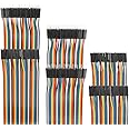
You need a lot of wires and 3.3V
This thing pretty much does everything. Very nice graphics and reasonable touch. For the money, can't be beat.I've only used a logic level shifter to 3.3V with this. Everything works fine when you use it.Pins of interest:CS is Chip Select (user defined)Reset is Reset (user defined)DC is DC (user defined)MOSI is MOSISCK is the ClockLED ties to VCC (3.3v)MISO is MISOThe Touch Screen is simplerThe SD Card slot need to have posts solderedOtherwise, very good value. Works great. Use the Adafruit ILI9341 library for the LCD.Use the Adafruit STMPE610 for the touchscreenUse the SD library for the SD card
T**.
Use buffer gates as level shifters for longer connection distances
These inexpensive TFT touchscreens work well once you learn what works and what doesn't. I recommend using level shifters (if using an Arduino) to decrease all OUTGOING DATA SIGNALS from 5V to 3.3V. The MISO / T_DO INCOMING DATA from TFT to Arduino does not need to be shifted up to 5V since Arduinos recognize voltages over 2.5-3.0V as HIGH. In order to allow further distance (longer connections) from Arduino to TFT, I had to scrap the bidirectional TXS0108E level shifters that are commonly used and switch to SN74AHCT125 buffer gates. These shift voltage unidirectionally (5V to 3.3V -- which is all that is needed) and are much quicker and output more amperage to overcome capacitance in the wires, allowing much longer distances between Arduino and TFT--great for SPI communication. Also, Vcc and LED voltage to TFT can be 5V, but all data signals should be 3.3V. Once I scrapped the bidirectional level shifters and went to the buffer gates, my connection distance increased from only 6-8 inches to over 30 inches.
C**R
Works fine once you get past a few gotchas
Let me state, it works, it works as expected and I like the display.Let me get you over a couple of gotchas. First off, no joke on the 3.3V logic. You can't use an UNO for testing, it just doesn't work. I can think of a chipset I haven't been able to cheat it but 5V = doesn't function (worked fine after I switched processors, I didn't cook mine).I got mine working on an Arduino MKR. I tied reset to the MKRs VCC, I plugged the display VCC into the 5V pin. I used the Adafruit ILI9341 library and the display test ran after I look the "LED" pin and tied it to pin 6 and did the told digitalWrite(6, HIGH); on the top line of setup();.I then tested the touch screen with the XPT2046 library, there is only one out there from memory. One note... the MISO/MOSI lines are NOT connected as some online walkthroughs state... so you'll need to switch wires over for bench testing. I used the example with IRQ and put my CS on pin 5 and IRQ on pin 4. The sensitivity of the display matched my expectations for a resistive touch screen (vs capacitive).For the hassle I prefer the Adafruit version but with a little extra effort it's worth the lower cost.
Trustpilot
3 days ago
1 month ago
2 months ago
1 day ago